First of all, tell me what is KERS?
KERS stands for ‘Kinetic Energy Recovery System’ and in short its main aim is to harness the kinetic energy of the vehicle (which is lost in form of heat under braking) , stores it in some other form energies(like electrical or rotational ) that can boost acceleration by pressing a button on the steering wheel under acceleration. Now a days this system is not very common in road-cars but it is extensively used in racecars. Actually the whole idea of harnessing the kinetic energy was invented way back in 50s when physicist Richard Feynman proposed an idea of storing vehicles kinetic energy by the use of flywheel but no serious attempts were made in field of energy recovery until 2006 when the FIA, F1’s governing body, elected to allow teams to integrate Kinetic Energy Recovery Systems (KERS) into their vehicles starting in the 2009 racing season. And this rule forced the engineers to brainstorm and come up with an efficient yet lite weight KERS system.
Okay, what are the different type of energy harnessing techniques ?
Well, working of KERS mainly depends upon the type of energy harnessing method they use. There are several different approaches for harnessing energy which are mentioned below-
- Mechanical Recovery ( By the use of flywheel which stores kinetic energy of the vehicle in form of rotational energy)
- Electrical Recovery (By the use of batteries or ultra-capacitors to store K.E. in form of electrical energy)
- Electromechanical Recovery( By the use of both flywheel and electric motor)
- Hydraulic recovery (By conducting pressurized hydraulic fluid into an accumulator during deceleration, then conducting it back into the drive system during acceleration)
Right then..could you explain to me in detail about each energy recovery system…?
Sure. Well, the anatomy and working of the KERS system depends upon its approach of recovery. So here we go..
Flywheel hybrid systems (KERS):
One of the first companies to put up their finance and faith in field of energy recovery and specially Mechanical energy recovery was Flybrid systems. And the story of formation of this company is as interesting as its name. The flybrid systems was co- founded by Hilton who was drivetrain engineer at Renault F1 and with his colleague Doug Cross who was design manager in the same team.
‘We sat down in the pub and said this is how big a job it is,’ Hilton recalls. ‘We worked out how much we thought it would cost to get to the point of a running demonstrator on an engine dyno – we thought we would have to get that far to sell it to anybody – and we discussed whether we had enough finance between us, and agreed we did.’ And so Flybrid Systems was born. And the name was derived from formula given below:
Flywheel + Hybrid= Flybrid
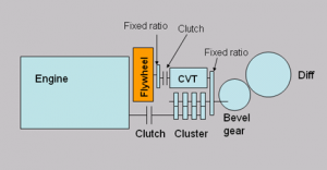
 Now let’s see the working of flywheel based energy recovery system. The system comprises a flywheel connected by a continuously variable transmission [CVT] to the drivetrain. If you move the CVT toward a gear ratio that would speed the flywheel up it stores energy. Conversely, if you move toward a ratio that would slow it down then it releases energy. Finally, a clutch separates the drive if the revs move beyond the limits of the system. But Flybrid’s innovations also address the need to create sufficient power storage density in a unit small enough and light enough for use in F1. To achieve this they upped the speed of the flywheel massively to 64,500rpm, which allows a smaller, lighter flywheel but also means it has to be contained in a very robust structure in case of failure. And to avoid the heat produce due to air friction at such a high speed they decided to put the flywheel in vacuum casing.
But at this point of time you might think, how can we get the same amount of energy by decreasing the mass and increasing the rotation of the flywheel?
Well, as we know that rotational energy of the spinning wheel is given by-
![]() where,
where,
- I is the moment of inertia of of the flywheel and
-
 is the Angular velocity
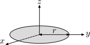
 Also moment of Inertia of inertia of the disc about the z axis as shown in figure is given by

so what what we conclude from the above formulas is that rotational energy is directly proportional to mass and squared times the angular velocity. So if we decrease the mass to half the rotational energy becomes half meanwhile if we double the angular velocity, rotational energy becomes four times so over all if decrease the mass to half and double the  , we get twice the energy as we are getting previously.
So that’s why they prefer a lite flywheel weighing of around 5 kg but such a high rotational speed. Still finding it difficult to understand?
Have a look at this video…
And that’s all we have on mechanical recovery and if you still feel their is still something I left out, or unexplained, feel free to kick my butt 😛 ( let me know! ) . Now lets see the fundamentals of electrical recovery, shall we
Electrical Hybrid (KERS):
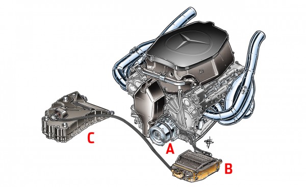
Most of the F1 teams use this KERS to recover energy as the mechanical recovery have some packaging issues. In essence a electrical KERS systems is simple, you need a component for generating the power, one for storing it and another to control it all. Thus electrical KERS systems have three main components: The MGU, the PCU and the batteries. All component are labeled in the figure given below:
A. MGU (Motor Generator unit)
Mounted to the front of the engine, this is driven off a gear at the front of the crankshaft. Working in two modes, the MGU both creates the power for the batteries when the car is braking, then return the power from the batteries to add power directly to the engine, when the KERS button is deployed.
B.PCU (Power Control Unit)
Typically mounted in the sidepod this black box of electronics served two purposes, firstly to invert & control the switching of current from the batteries to the MGU and secondly to monitor the status of the individual cells with the battery.
C. Batteries
The batteries are the arrays of lithium-ion cells and approximately same as your cell phone batteries. Made up of around 40 individual cells, these batteries would last two races before being recycled. Being charged and discharged repeatedly during a lap, the batteries would run very hot and needed cooling, this mainly took the form of oil or water cooling, and again McLarens example had them pack water cooled with its own pump and radiator.
So this was all about setup of Electrical hybrid KERS, now lets see how it works?
When driver applies the break, some part its K.E. is converted into electrical energy by the help MGU, as the MGU unit act as a generator. This electrical energy is stored into the batteries via PCU which monitors the amount of energy harnessed by KERS system as FIA has restricted on the amount of energy that could be re-used, only 400kJ could be stored, which when used for 6.7s per lap, the car gained some 80hp. So when driver presses the button electrical energy which is stored in the batteries is again converted into mechanical energy by the help of MGU which act as a electrical motor this time. As of 2014(F1), the power capacity of the KERS units will increase from 60 kilowatts (80 bhp) to 120 kilowatts (160 bhp). This will be to balance the sport’s move from 2.4 litre V8 engines to 1.6 litre V6 engines. You can better understand the working of the Electrical KERS by watching this video:
Electromechanical KERS:
This type of KERS came into discussion when Williams (F1 team) suggested a recovery system based on both fly wheel and electrical motor or say MGU (Motor Generator Unit). In this system, when driver applies the break, some part of vehicles K.E. is converted into electrical energy by the help of MGU now this electrical energy is passed to another MGU which act as a motor at that time and speeds up the flywheel attach to it to a very high 70,000 RPM. Now when driver presses the button on his steering, the rotational energy of the fly wheel is converted back into electrical energy by the help of MGU and that electrical energy is used by another MGU(acting as a motor) which speeds up the crankshaft and hence the whole car. The above system is explained in the following video…
So that was all about the electrical, mechanical and electromechanical KERS, now lets move onto the last type of KERS i.e. Hydraulic.
Hydraulic KERS:
A hydraulic KERS uses a pump in place of the MGU and an accumulator in place of the batteries. So when driver applies the brake the the rotational energy is harnessed by the pump as it pumps the fluid into the high pressure accumulator from the fluid reservoir. Now when driver pushes the KERS button the high pressure fluid flows from high pressure accumulator to the pump(which now act as a hydraulic motor) and speeds up the vehicle. Hydraulic accumulators are already used in heavy industry to provide back up in the event of failure to conventional pumped systems. Using filament wound carbon fibre casing, an accumulator of sufficient capacity could be made light enough to fit into the car. McLaren(F1) had prepared just such an energy recovery system back on the late 90s, but it was banned before it could race (low FIA cap on energy storage). The video attached below, shows you the working of Hydraulic hybrid vehicle(HHV) who’s working is very close to the working of Hydraulic KERS used for racing purpose like F1…
